The Lisp Badge mini computer has turned out to be quite useful and fun for little hardware hacking projects. Its designer, David Johnson-Davies, suggested that the SMART Response XE would make a good off-the-shelf uLisp computer, eliminating the need to build one from scratch.
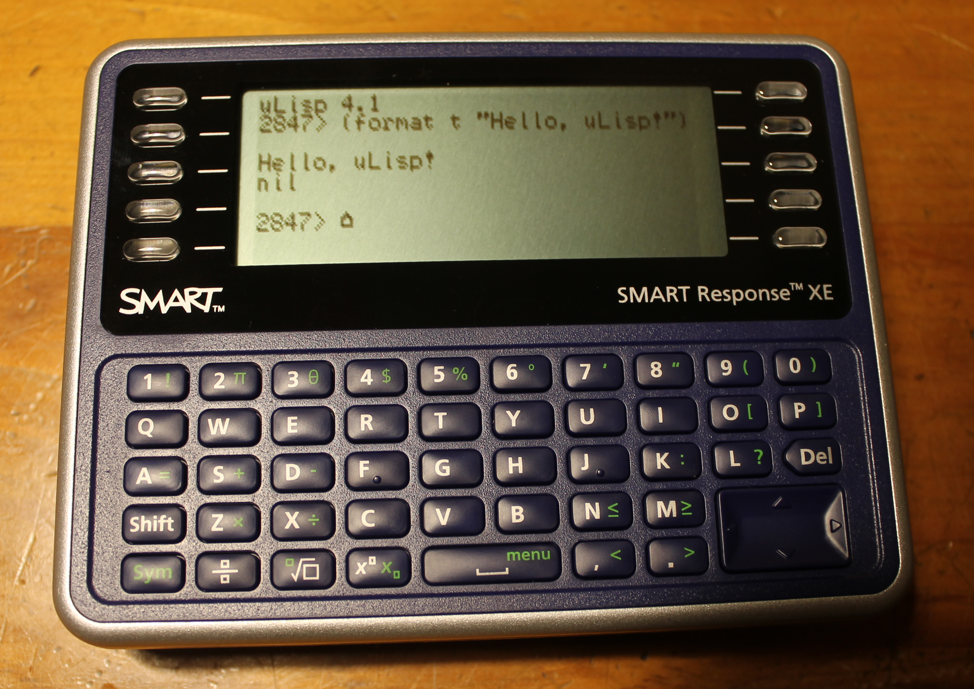
I ordered a few SMART Response XEs from an auction site to see what was possible. I found Larry Bank‘s excellent Arduino library and fdufnews‘s schematics, which provided a great starting point. With guidance from David, I completed an initial uLisp port:
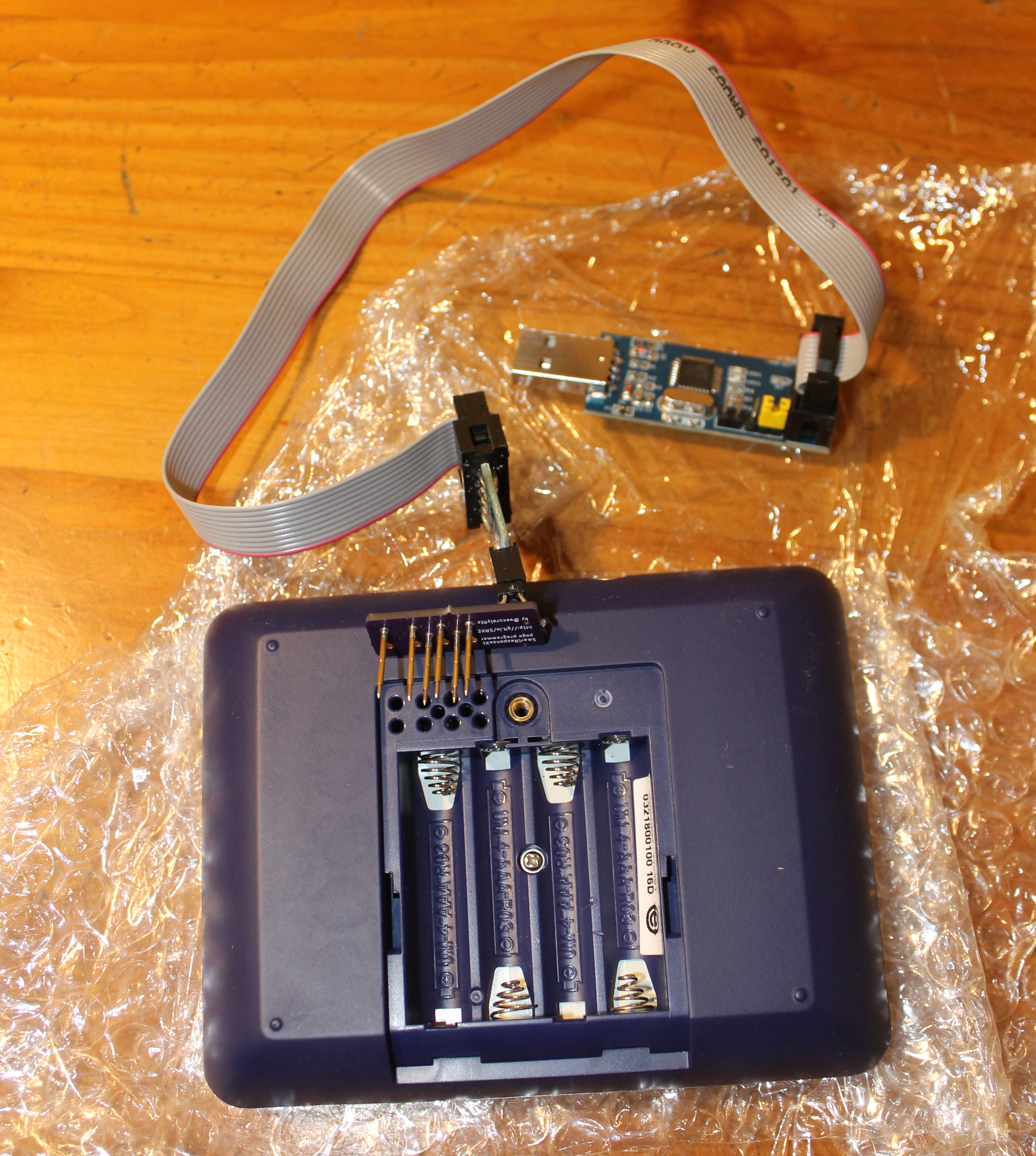
To load the code, I use an ISP programmer and a special PCB with POGO pins:
On Debian, I run:
make ispload
to load LispBadge.ino without a bootloader.
The SMART Response XE uses the ATmega128RFA1 microcontroller, which has a ZigBee IEEE 802.15.4 transceiver. David and I are discussing adding uLisp functions to make use of this capability.
Exciting stuff — thanks for sharing!
Do you plan to make more details available later so people can reproduce this and/or sell such devices on Tindie?
Clarification: As in YOU selling the devices, not others capitalizing on your work. I’m interested in personal use and otherwise supporting your project.
Interesting idea, I hadn’t considered that.
Everything required is published in the links throughout the post, however putting it all together is challenging.
While writing this, I did find the ones being sold with BASIC pre-installed. As far as I know, you can’t reprogram them without the POGO adapter.
The POGO pins are long and difficult to align. For an easy-to-use solution, there would need to be USB dongle with an ATmega128RFA1, for wireless reprogramming (generic ZigBee dongles don’t support the required communication protocol, apparently). Larry Bank already created a bootloader with wireless support that could be installed one-time via the POGO pins. I have an SRXE that I cracked open that could work in the “wireless programmer” capacity. But it’d be nicer to have a dedicated dongle.
@Thomas , your git is broken, can’t make any file,
“Arduino-Makefile/Arduino.mk: No such file or directory”
In the checkout directory try “git submodule update –recursive –init” to clone the submodules.
Hi Thomas,
I am working on building the cable part. I’m stuck on what to do between the pogo board and the cable itself. Do you have any photos of that section or more instructions? Sorry if this is a very basic question, I’m a bit new to this kind of project. Thanks for the help in advance.
Christina
Hi Christina,
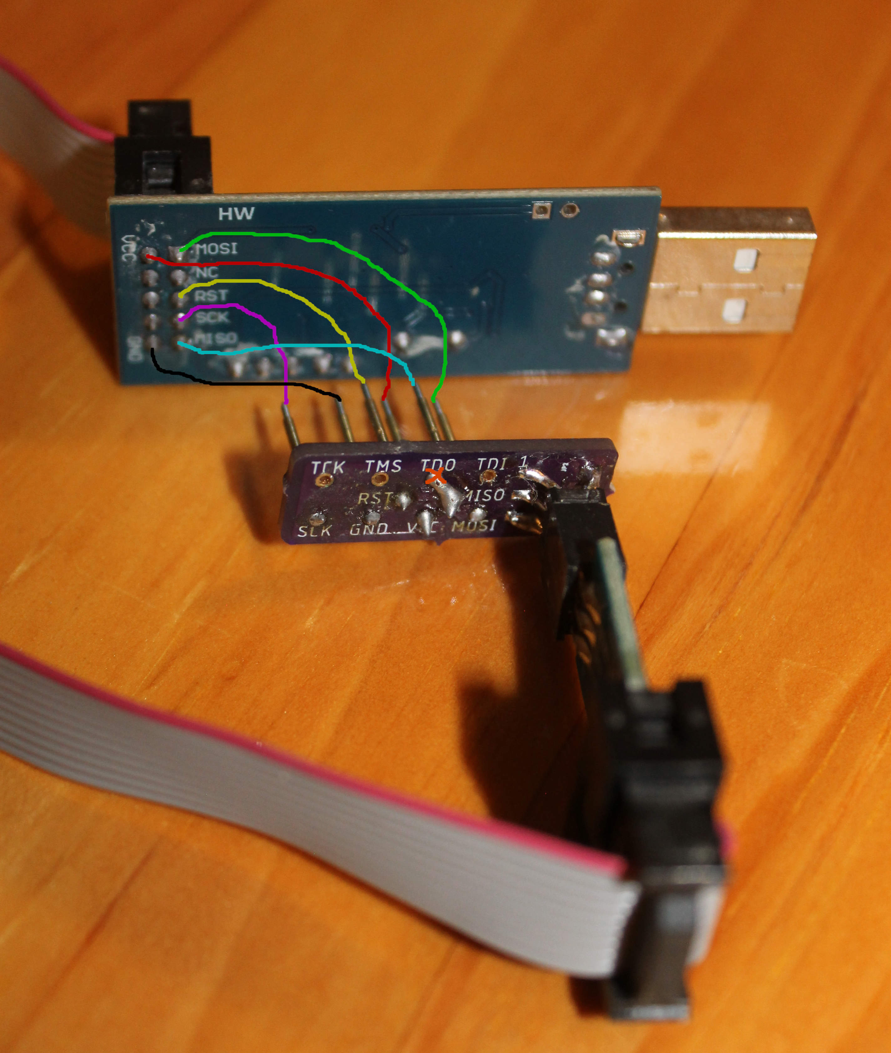
The cable needs to connect six pads on the ISP board to the corresponding six POGO pins. For example, the pad on the ISP board labelled “MOSI” should be connected, via one of the cable’s wires, to the POGO pin labelled “MOSI”. The ISP cable has a six pin connector on the end to which you will connect the POGO board. You need to solder the complementary six pin connector to the POGO board. The POGO board’s documentation suggests some suitable parts: securelyfitz/smartresponse. Using a multimeter you can verify continuity from each of the POGO pins to the same-named ISP board pad.
Here is a picture of my setup with the logical connections overlaid (the soldering job is not my best; the solder connection to the TDO pad (under the orange X) is harmless but should not be there; I did not have a surface mount (SMT) six pin header so I used a through-hole one I had lying around):
Let me know how it goes.
Thomas